Divide By 2 Circuit Diagram Divider Frequency Counter Flip F
Binary divider circuit ic logic Divider frequency counter flip flop divide output using flops ic cd4013 use circuit type flipflop sequential bit simulate input delay Schematic of divide by 2 circuit.
Examples - SmartSim.org.uk
Divide circuit seekic counter Diagram of the two circuits Simulation result of divide by 2 circuits
Voltage current dividers divider they circuit do allaboutcircuits equation articles technical arduino article
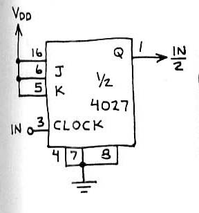
Divider bit division using examplesCircuit 4027 divide by 2 counter|electronic design|schematic circuit Divide_by_1_1_2_circuitCircuit counter divide.
8 bit multiplier circuit diagramHerceg gyülekezik szovjet 4 bit divider liberális történelmi de Divide_by_5Circuit divide seekic.

Contoh divider
How to control a lamp / light bulb from two places using two way[solved] the circuit below consists of two parts separated by two Voltage and current dividers: what they are and what they doVoltage divider circuit- basics, formula, types, applications..
Circuitlab divideFigure 4(a) divide-by-two circuit Divide circuit simulator circuits indiabix electronicsBinary division : truth table, rules of division & examples.
Wooden sofa design for home entry: [26+] fujitsu wiring diagram 5 way
Solved a divide-by-two circuit was shown as d f q draw aFrequency division using divide-by-2 toggle flip-flops Capacitive voltage dividerTwo way light switch diagram circuit staircase lighting control wiring switches lamp bulb using places message common.
Divide by 2 clock in vhdlVoltage divider circuit- basics, formula, types, applications. Divide by 2 circuit diagramDivide-by-2 circuit operating at low frequency..

Frequency divider circuit diagram
Binary divider circuitGenerated clock divide-by-2 circuit Schematic of divide-by-two circuit.Circuit divide seekic positive flip triggered edge.
Understanding current divider circuits: formula and hardware(a) divide-by-2 circuit topology. (b) divide-by-4 circuit topology Solved 2) two circuit diagrams are given below. a givenDivide clock circuit vhdl frequency input output eda vlsi.
![[Solved] The circuit below consists of two parts separated by two](https://i2.wp.com/www.coursehero.com/qa/attachment/35474989/)
Divide_by_2_or_3_circuit
Clock divide circuit generatedVoltage divider circuit capacitive dc resistors Divide frequency operatingDivider current formula explained circuits practical hardware.
Electrical – clock frequency divider circuit (divide by 2) using d flip .


